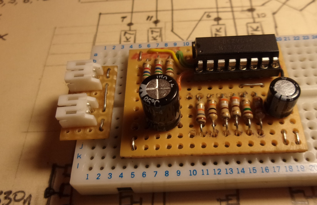
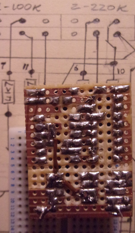
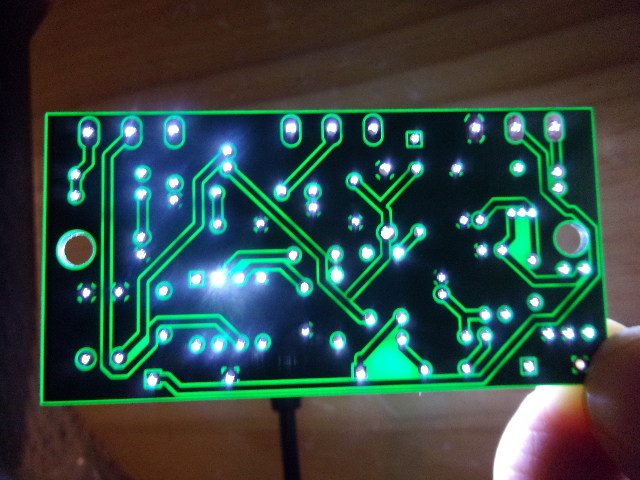
Maybe not such a good idea building circuitry in reverse -
the VCA (LM13700N) circuit above was completed back in February!
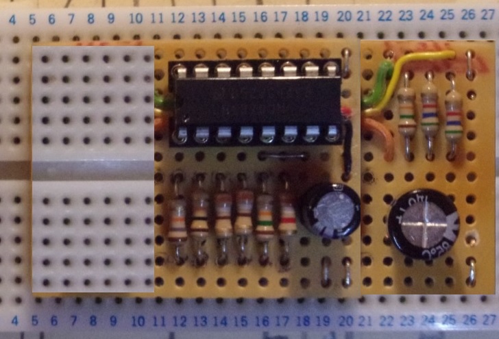
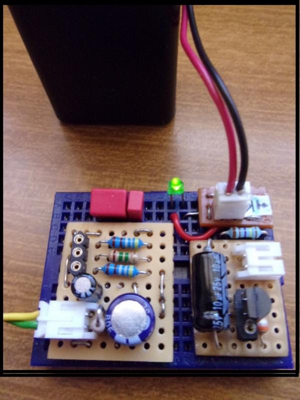
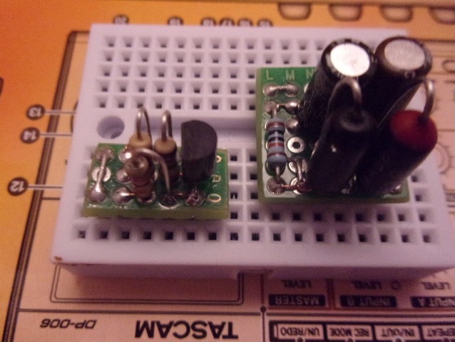
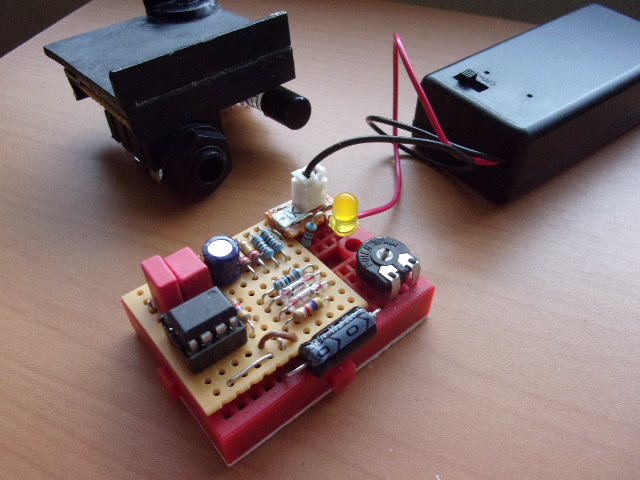
VCA Input Circuit
The source (V)oltage for the output (A)mplifier can be used as a stand alone
effect (with just two additional components) and has quite a good
warm fuzzy lo-fi sound ...
However, this fairly straightforward circuit does have quite
a high signal to noise ratio. And although I'm sure the VCA output
will noise gate this, to some extent, it is still good to know there
is plenty of scope for a better more sophisticated (V) input.
(I have an NE570N compander IC in the junk box that could do the job.)
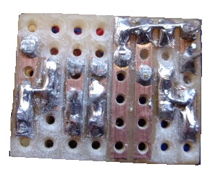
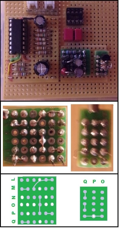
The best laid plans -
Once the input jack socket and switch assembly was finished
it was supposed to be the housing platform for the input circuit board,
mounted onto the upper side.
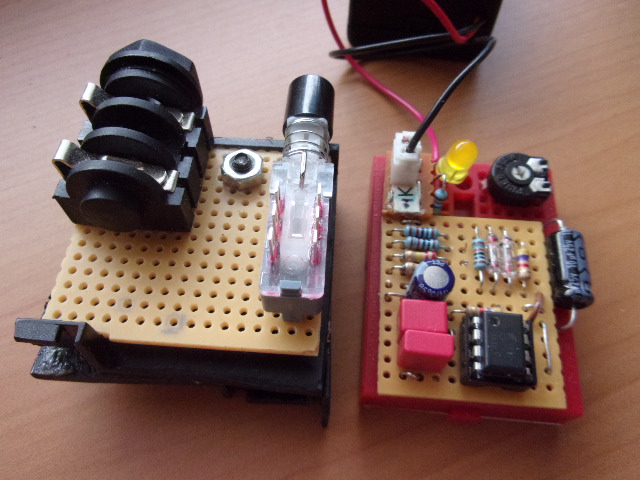
But, as it turns out there just might be room for the components (currently in the post) on
the available space next to and between the jack socket and switch.
Which would free up the upper side of the assembly for the Control Voltage smoothing/rectifier boards, and
VCA output Amplifier chip.